Hello GoPro Karma Pilot!
Join our Go Pro Karma community today!
Sign up

Karma refusing to pair - Reverse engineering investigation

If you hit enter it should show you a login screen. If that doesnt work come over to the discord server, I think there was someone there who had an issue with putty not responding to keyboard input. I think they just changed to a different terminal emulation software.
Finally, My Karma is flying... Thank you.
 
  • Like
Reactions: Ninja27
Is anyone able to provide a MD5 hash for Karma_boot_SD.img ?

I keep getting no data in the serial terminal when TP1 is bridged to TP2, the failed to boot log appears when TP1 is not bridged

I have verified many times continuity from microSD slot to J14.
Hi,
My MD5 checksum is:

MD5 hash of Karma_boot_SD.img:
a40e5a7800a98e7ccce184e34b554751
 
  • Like
Reactions: Ninja27
Try moving the resistor so that it is only used on the wire for TP1.

We have found that some units dont like the resistor connected between power and the SD slot, the voltage drop appears to be to great and the SD card doesnt boot.
Sometimes it is necesarry to try another microSD card, from another brand, of you will.
The initialisation procedure for (micro)SD cards is not always working perfect for some SD cards. Another SD card can fix this. I did not use the resistor because a standard MicroSD card needs 3.3 Volt at Vdd pin. Only MicroSD cards with the label "LV" printed on them can work with 1.8 Volt. So for generic microSD cards, do not use the resistor, otherwise the SDcard will not do anything.

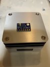
Please be aware of the orientation of your SD card slot when you start soldering it onto the Arm-switch board. Better safe than sorry, find the pinout picture of MicroSD card on internet, and insert the card in the socket, and pay attention on the pin numbers where they connect with the socket. GND and Vdd are important to connect them the right way. Otherwise you can fry components on your drone board.

What I did:
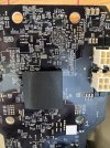
Put the drone on the table/workbench so, that gimble side is front side facing, and you look onto the board from above. Take the upperleftmost pin of JTAG and solder a thin wire on here. On the other end of this wire, you connect two more wires (so 3 wires connect to eachother, junction as you will). The two loose wire ends: On one, you solder the 1K resistor, then the other side of the resistor, solder a wire on here with a thin probe on it. You will use this to put it on the very tiny SMD resistor so select SDcard boot mode on startup/reset of the drone. If it boots fro SDcard you can take the probe away.

The other loose wire, you solder that to FB36 , the right solder point, next to connector to the SD card board.

I have used the JTAG leftmost pin, as 3.3V source, because it is much easier to solder on here. Use a fine and clean solder tip, and first ad a very little fresh new solder to the JTAG pin first, after that solder the wire on here.

Use a very good light source above the drone where you are working on, Good light - and patience - is golden for the fine work you need to do. Try to solder quickly and not keeping the solder iron too long in the solder point, it will damage a solder point or trace of the board. You do not want that.
 
Last edited:
  • Like
Reactions: Ninja27
Hi,
My MD5 checksum is:

MD5 hash of Karma_boot_SD.img:
a40e5a7800a98e7ccce184e34b554751
I encountered the same issues and attempted various solutions. It's crucial to carefully inspect the microSD connection, examining each pin individually. The most effective method involves desoldering the microSD slot and giving it another try. Upon desoldering, you'll be able to identify any improperly soldered pins. Thanks to the photo shared by a member named "account deleted" on 10/24. Following the example photo, I removed the cover, resoldered each pin while ensuring a secure connection by pressing on each one. It's essential to solder the cover plate back in place; my attempt without doing so was unsuccessful. I hope this information proves helpful.IMG_2023-10-24-13-59-10-624.jpgIMG_2023-10-24-14-07-43-709.jpg
 
Although I succeeded in rewriting the boot sector, I got an error message saying that I couldn't take off due to an abnormality in baro.I peeled it off with a hot plate from a certain module and pasted it, and it worked.
GY-63 MS5611-01BA03
 

Attachments

  • IMG_6581.jpeg
    IMG_6581.jpeg
    1.5 MB · Views: 17
  • IMG_6312.jpeg
    IMG_6312.jpeg
    2.3 MB · Views: 16
  • Like
Reactions: Ninja27 and edk160
Although I succeeded in rewriting the boot sector, I got an error message saying that I couldn't take off due to an abnormality in baro.I peeled it off with a hot plate from a certain module and pasted it, and it worked.
GY-63 MS5611-01BA03
Thank you for sharing this solution ! Do you know if there is hardware schematic of the Karma Drone available somewhere ? And also hardware schematic of the controller ?

How did you de-solder the old barometer and solder the new barometer onto the mainboard ? With hot air? or very fine solder iron tip ?
Unfortunately I don't know where the schematic is. I recognized Burro because of its unique appearance. I used a heat gun to remove it, but it was very difficult.
 
Unfortunately I don't know where the schematic is. I recognized Burro because of its unique appearance. I used a heat gun to remove it, but it was very difficult.
Heat gun or hot air soldering station ? I assume you mean hot air soldering station ? Thanks for the info , I have one with a broken baro so will try this as well.
 
  • Like
Reactions: Boko
Heat gun or hot air soldering station ? I assume you mean hot air soldering station ? Thanks for the info , I have one with a broken baro so will try this as well.
Is the barometer prone to fail suddenly ? If so, I probably need to buy some for spare, just in case. And a hot air rework station :)
 
Is the barometer prone to fail suddenly ? If so, I probably need to buy some for spare, just in case. And a hot air rework station :)
I have only seen one faulty one so far. I have heard of a second one that was faulty. So I guess they do fail but its seems to be rare
 
No , Im an Aussie just like you, how quickly you forget, lols

The last rev c board I fixed it took about 15 minutes from start to finish, Luis appears to be charging people anywhere from $300 - $500 AUD to fix the issue. But he wouldnt be using our technique as it is very unique. Im planning on doing a video on the process when I get another version c board in for repair. That way people can have a go at it themselves or go to an electronics repair shop and say "do this".
Is this only available to rev C onwards

I have revision B
 
Can anyone recommend where to get the sdcard board. I live in the UK
 
Hi,

I am trying to fix my drone with a pairing issue.
So I plug my laptop to the serial debug port and I can see the famous error NAND boot failed.

So I have soldered a micro sd adapter on the arm board where there is a empty micro sd card location.

But the drone won't boot on sd card (I put 3v3 through a 1k resistor on the resistor near the big chip and I bridge FB36 to power the sd card slot.

I think I am pretty close to get it work because I probe with my oscilloscope the clock pin of the sd card and when I boot with the 1k resistor trick I can seee the clock running (nearly 300kHz).
Without the 1k resistor trick the clock is not running so I think eveything looks good but drone won't boot on sd always the NAND boot mode.

I tried another sd card same thing.

The only thing is that my drone is a REV E. Is the trick work with a REV E ?

PS : sorry for my english I am french

Thanks in advance for answers.

Eric
Hi, come over to the Discord server, there are many people there who can help you in real time.


They will want to know what happens on the screen when you try and boot from the SD card? Is it now blank or do you still get the NAND error (Im going to assume its blank).

What size is the SD card ? some people have found that using a different image burning software works for them.

Is the resistor only on the voltage line that goes to the TP1 ? If its on the 3.3 volts to FB36 then its known to cause issues.

It would be worth checking to make sure the SD card is soldered correctly, many people who try this method have issues. There is a picture somewhere on its pin outs to the arm board.
 
Yes most of the time it's blank when I try to boot on SD card.
When I boot normally I always have a display and the NAND boot error.

I tried both sd card 4GB and 16GB.

I will try another software to burn image (I used win32diskimager as you suggested).

Yes the resistor is only on TP1. 3v3 goes directly to sd card (I bridge FB36 with a wire).
 

Members online

No members online now.

Forum statistics

Threads
1,040
Messages
7,646
Members
2,573
Latest member
raith11458